Lesson 4 description
Date: 23 september 2010
Duration of activity: 13.15 - 18.00
Group members participating: Nikki & Knud
GOALS for lesson 4
-In this lab session we will try to make a self-balancing LEGO robot inspired by Steve Hassenplug's origional Legway controlled by the RCX, [1]. Two examples of self-balancing robots controlled by the NXT is Philippe Hurbain's NXTway, [2], and Brian Bagnall's balancing robot, [3]. Use these as inspirations to build and program your own robot.
Subgoals:
- Build the robot
- Create balancing algorithm and get the robot to balance
1. Build the robot
Follow the building instructions on http://www.philohome.com/nxtway/bi_nxtway.htm
2. Create balancing algorithm and get the robot to balance
We will use a PID-controller as basis for the balancing algorithm and use the supplied references as inspiration. We will also try to avoid the motorblock by making the balancing smooth by tweaking the coefficients Kp, Ki and Kd. If time allows it, we will implement live tuning over bluetooth (http://en.wikipedia.org/wiki/PID_controller#Manual_tuning). If we are not able to achieve a smooth balancing, we will trade the motorblock for imprecision in the actuators by plugging the actuators into socket A and C (uses two different H-bridges, thus avoiding the motorblock)
The balance test will be done on non reflecting surface and in a relative dark room so the ambient light doesnt influence on the sensor.
A test could also be done with the robot connected to charger connected to the power grid to insure that theres full charge on the motor so it has enough power to reactly.
Instead of the light sensor, perhaps the sonic sound sensor used previously to measure distance could be used.
Results
1. Build the robot
The Robot build after following the previously mentioned guide:

A small modification that we made to change the mass middle point to reduce oscillation:

2. Create balancing algorithm and get the robot to balance
We decided to write our own PID regulator in java to better insure that we understand it.
Proportional Part:
Its a coefficient that's multiplied of the current error, Kp * error so we now have a value that proportional to the error, so the P part adjust the control signal proportion to the error, if the error is big then we have make a big change to control signal u which is the output of regulator and in our case the input to the motors or the power to motors.
Integration Part:
We found that it can be approximated with the Trapezoidal rule (http://en.wikipedia.org/wiki/Trapezoidal_rule) with the following formula:
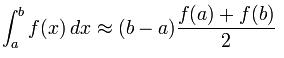
however we can just write f(a) + f(b) since the timedifference (b-a)*(1/2) will just be constant and therefore a part of a constant or coefficient, the Ki that can be tweaked. In other words we can just add the current error with previous error, error + preverror.
The integration part changes the control signal u according to error of the last time or the previous error, example if the error is zero and we are spot on then there wont be added anything to it this is useful for finding the right steady state level of the desired signal.
Differentiation Part:
The differentiator part concerns the slope of the error or the rate of change of the error. That can be found with:
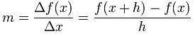
again we just write f(x+h)-f(x) since (1/h) is constant and can be tweaked with Ki coefficient.
However we don't know the future value of the error so we have to be a step behind and instead write the current error subtracted with the previous one. Error - Preverror.
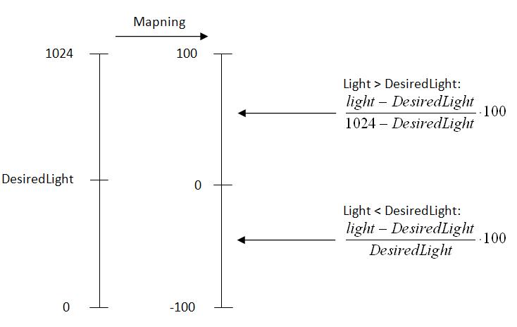
Datalogging & Mapping:
We had an idea to make real time monitoring of the Position and power with datalogging and plot it, for it to look like the graphs on page 187 and 189 in the printout delievered from “Robotic Exploration A Hands-On Introduction to Engineering” from Fred G. Martin so we would be able to see visually how well the respective terms in the PID regulator are performing and tweak the PID coefficients accordingly.
Our implementation of the PID-controller:
static void pidControl(int desiredLight) throws Exception {
// PID values
final float Kp = 4f;
final float Ki = 0f;
final float Kd = 1.83f;

DataLogger dl = new DataLogger("Sample.txt");
int scalaPlus = (1024 - desiredLight);
int scalaMinus = desiredLight;

_ls.setFloodlight(true);

int light, power;

float error, prev_error, Pout, Iout, Dout;
error = prev_error = Pout = Iout = Dout = 0;

LCD.drawString("Light: ", 0, 1);
LCD.drawString("Desired light: ", 0, 2);
LCD.drawString("Error:    ", 0, 3);
LCD.drawString("Power:    ", 0, 4);

while (! Button.ESCAPE.isPressed())
{
light = _ls.getNormalizedLightValue();

error = light - desiredLight;

// Proportional term
Pout = Kp*error;

// Integral term
Iout = Ki* ( (prev_error + error)/2 );

// Derivative term
Dout = Kd * (error - prev_error);

prev_error = error;

power = Math.round(Pout + Iout + Dout);

// Sample light on -100 0 100 scale
if(light>desiredLight) {
dl.writeSample(power, ((light-desiredLight)/scalaPlus) * 100);
} else {
dl.writeSample(power, ((light-desiredLight)/scalaMinus) * 100 );
}

if ( error > 0 )
{
power = Math.min(power,100);
Car.forward(power,power);
LCD.drawString("Forward ", 0, 5);
}
else if (error < power =" Math.min(Math.abs(power),100);">
One of the problems we encountered when running the code in practice on the robot, is that when the robot would tilt backwards it would not back fast enough on the wheels to corrigate for the tilt and would therefore tilt backwards completely.
http://www.liscom.dk/lego/Lab4Balance/Lab4Balance.java
http://www.liscom.dk/lego/Lab4Balance/BlackWhiteSensor.java
http://www.liscom.dk/lego/Lab4Balance/DataLogger.java
Ingen kommentarer:
Send en kommentar